Introduction
Documentation
Syntax
Autoexport from the XML-Schema for element IL:switchIL of railML ® version 3.3 |
| Documentation
|
The switch is a track asset where a train can change from one track to another. Here the functional aspects for interlocking operation are considered.
Extends the infrastructure::switch for IXL purposes. The graph model from RailTopoModel allows the definition of connections between tracks. Thus, one can include or exclude connections between tracks. The name SwitchIL is chosen to reconcile US nomenclature and to avoid a naming conflict with infrastructure domain.
|
| Subschema
|
interlocking
|
| Parents*
|
switchesIL
|
| Children
|
assetName (0..*), belongsToOperationalPoint (0..1), branchLeft (0..1), branchRight (0..1), branchTip (0..1), connectedToPowerSupply (0..1), designator (0..*), elementState (0..*), hasCommand (0..*), hasFoulingTrainDetectors (0..*), hasGaugeClearanceMarker (0..*), hasIndication (0..*), hasPositionRestriction (0..1), hasTvdSection (0..1), refersTo (1..2), relatedMovableElement (0..1)
|
Attributes:
- preferredPosition: This is the preferred position of the switch which it is switched to when not in use or in case of both positions required for flank protection. (optional;
xs:string)
- Possible values:
- indifferent: The position does not matter for the use.
- left: position of a switch for use of left branch
- right: position of a switch for use of right branch,
- isKeyLocked: One of boolean true or false. True means that the switch is clamped either mechanically or by any electric or electronic means. The interlocking shall never attempt to throw a clamped switch. (optional;
xs:boolean),
- localOperated: This gives information, whether the derailer is locally operated independent of any <signalBox>. (optional;
xs:string; patterns: other:w{2,}; consider Dev:UsingAny too.)
- Possible values:
- electrical: For the local operation an electrical drive is used.
- mechanical: The local operation is made by means of mechanics, e.g. lever with counterweight.
- none: There is no possibility of local operation of this device.,
- maxThrowTime: Maximum time in milliseconds during which the IL can drive the element. If it has not reached end-position before this timer expires, the interlocking stops throwing as to prevent damage. (optional;
xs:duration),
- numberOfBladeSwitchActuators: number of switch actuators controlled from interlocking to throw the switch blades, 0 means no direct operation from the interlocking (optional;
xs:nonNegativeInteger),
- numberOfFrogSwitchActuators: number of switch actuators controlled from interlocking to throw the frog nose(s), 0 means no movable frog (optional;
xs:nonNegativeInteger),
- returnsToPreferredPosition: The automatic normalisation attribute is closely related to the preferred position. Whether or not the IL returns the element to its preferred position depends on this parameter. E.g. a derailer that is modelled as ... preferredPosition=engaged autoNormalisation=true ... will return to its engaged position when released. A switch modelled as preferredPosition=right autoNormalisation=false... will not automatically return to the right position when released. This combination of attributes is useful for geographical interlockings that automatically determine the preferred routes given the preferred position of intervening switches. (optional;
xs:boolean),
- typicalThrowTime: typical throw time is the average time it takes between the moment the IL receives the call and the element reaches the new position. Switch throwing adds a delay to route setting that is of great interest to the use case simulation. For this purpose, we add an attribute typicalThrowTime that allows capacity planners to estimate the influence of slow throwing switches on train traffic. Note that this excludes controller (OCS) processing time and communication between controller (OCS) and interlocking. (optional;
xs:duration),
- elementNumber: element number for internal referencing in the engineering data (optional;
xs:nonNegativeInteger),
- id: the identifier of the object; this can be either of type xs:ID or UUID (obligatory;
xs:ID); compare: Dev:Identities
|
*Notice:
Elements may have different parent elements. As a consequence they may be used in different contexts.
Please, consider this as well as a user of this Wiki as when developing this documentation further.
Aspects that are only relevant with respect to one of several parents should be explained exclusively in the documentation of the respective parent element.
|
Autoexport from the XML-Schema for element IL:switchIL of railML ® version 3.2 |
| Documentation
|
The switch is a track asset where a train can change from one track to another. Here the functional aspects for interlocking operation are considered.
|
| Subschema
|
interlocking
|
| Parents*
|
switchesIL
|
| Children
|
assetName (0..*), belongsToOperationalPoint (0..1), branchLeft (1..1), branchRight (1..1), branchTip (0..1), connectedToPowerSupply (0..1), designator (0..*), hasCommand (0..*), hasFoulingTrainDetectors (0..*), hasGaugeClearanceMarker (0..2), hasIndication (0..*), hasPositionRestriction (0..1), hasTvdSection (0..1), refersTo (1..2), relatedMovableElement (0..1)
|
Attributes:
- preferredPosition: This is the preferred position of the switch which it is switched to when not in use or in case of both positions required for flank protection. (optional;
xs:string)
- Possible values:
- left: position of a switch for use of left branch
- right: position of a switch for use of right branch,
- isKeyLocked: One of boolean true or false. True means that the switch is clamped either mechanically or by any electric or electronic means. The interlocking shall never attempt to throw a clamped switch. (optional;
xs:boolean),
- localOperated: This gives information, whether the derailer is locally operated independent of any <signalBox>. (optional;
xs:string; patterns: other:w{2,}; consider Dev:UsingAny too.)
- Possible values:
- electrical: For the local operation an electrical drive is used.
- mechanical: The local operation is made by means of mechanics, e.g. lever with counterweight.
- none: There is no possibility of local operation of this device.,
- maxThrowTime: Maximum time in milliseconds during which the IL can drive the element. If it has not reached end-position before this timer expires, the interlocking stops throwing as to prevent damage. (optional;
xs:duration),
- numberOfBladeSwitchActuators: number of switch actuators controlled from interlocking to throw the switch blades, 0 means no direct operation from the interlocking (optional;
xs:nonNegativeInteger),
- numberOfFrogSwitchActuators: number of switch actuators controlled from interlocking to throw the frog nose(s), 0 means no movable frog (optional;
xs:nonNegativeInteger),
- returnsToPreferredPosition: The automatic normalisation attribute is closely related to the preferred position. Whether or not the IL returns the element to its preferred position depends on this parameter. E.g. a derailer that is modelled as ... preferredPosition=engaged autoNormalisation=true ... will return to its engaged position when released. A switch modelled as preferredPosition=right autoNormalisation=false... will not automatically return to the right position when released. This combination of attributes is useful for geographical interlockings that automatically determine the preferred routes given the preferred position of intervening switches. (optional;
xs:boolean),
- typicalThrowTime: typical throw time is the average time it takes between the moment the IL receives the call and the element reaches the new position. Switch throwing adds a delay to route setting that is of great interest to the use case simulation. For this purpose, we add an attribute typicalThrowTime that allows capacity planners to estimate the influence of slow throwing switches on train traffic. Note that this excludes controller (OCS) processing time and communication between controller (OCS) and interlocking. (optional;
xs:duration),
- elementNumber: element number for internal referencing in the engineering data (optional;
xs:nonNegativeInteger),
- id: unique identifier (obligatory;
xs:string; patterns: (urn:uuid:)?[0-9a-fA-F]{8}-[0-9a-fA-F]{4}-[0-9a-fA-F]{4}-[0-9a-fA-F]{4}-[0-9a-fA-F]{12}|{[0-9a-fA-F]{8}-[0-9a-fA-F]{4}-[0-9a-fA-F]{4}-[0-9a-fA-F]{4}-[0-9a-fA-F]{12}}); compare: Dev:Identities
|
*Notice:
Elements may have different parent elements. As a consequence they may be used in different contexts.
Please, consider this as well as a user of this Wiki as when developing this documentation further.
Aspects that are only relevant with respect to one of several parents should be explained exclusively in the documentation of the respective parent element.
|
Autoexport from the XML-Schema for element IL:switchIL of railML ® version 3.1 |
| Documentation
|
The switch is a track asset where a train can change from one track to another. Here the functional aspects for interlocking operation are considered.
|
| Subschema
|
interlocking
|
| Parents*
|
switchesIL
|
| Children
|
any (0..*), branchLeft (1..1), branchRight (1..1), connectedToPowerSupply (0..1), designator (0..1), hasFoulingTrainDetectors (0..*), hasGaugeClearanceMarker (0..2), hasPositionRestriction (0..1), hasTvdSection (0..1), refersTo (1..1), relatedMovableElement (0..1)
|
Attributes:
- preferredPosition: This is the preferred position of the switch which it is switched to when not in use or in case of both positions required for flank protection. (optional;
xs:string)
- Possible values:
- maxThrowTime: Maximum time in milliseconds during which the IL can drive the element. If it has not reached end-position before this timer expires, the interlocking stops throwing as to prevent damage. (obligatory;
xs:duration),
- typicalThrowTime: typical throw time is the average time it takes between the moment the IL receives the call and the element reaches the new position. Switch throwing adds a delay to route setting that is of great interest to the use case simulation. For this purpose, we add an attribute typicalThrowTime that allows capacity planners to estimate the influence of slow throwing switches on train traffic. Note that this excludes controller (OCS) processing time and communication between controller (OCS) and interlocking. (optional;
xs:duration),
- returnsToPreferredPosition: The automatic normalisation attribute is closely related to the preferred position. Whether or not the IL returns the element to its preferred position depends on this parameter. E.g. a derailer that is modelled as ... preferredPosition=engaged autoNormalisation=true ... will return to its engaged position when released. A switch modelled as preferredPosition=right autoNormalisation=false... will not automatically return to the right position when released. This combination of attributes is useful for geographical interlockings that automatically determine the preferred routes given the preferred position of intervening switches. (optional;
xs:boolean),
- isKeyLocked: One of boolean true or false. True means that the switch is clamped either mechanically or by any electric or electronic means. The interlocking shall never attempt to throw a clamped switch. (optional;
xs:boolean),
- numberOfBladeSwitchActuators: number of switch actuators controlled from interlocking to throw the switch blades, 0 means no direct operation from the interlocking (optional;
xs:nonNegativeInteger),
- numberOfFrogSwitchActuators: number of switch actuators controlled from interlocking to throw the frog nose(s), 0 means no movable frog (optional;
xs:nonNegativeInteger),
- id: unique identifier (optional;
xs:ID; patterns: (urn:uuid:)?[0-9a-fA-F]{8}-[0-9a-fA-F]{4}-[0-9a-fA-F]{4}-[0-9a-fA-F]{4}-[0-9a-fA-F]{12}|{[0-9a-fA-F]{8}-[0-9a-fA-F]{4}-[0-9a-fA-F]{4}-[0-9a-fA-F]{4}-[0-9a-fA-F]{12}}); compare: Dev:Identities
|
*Notice:
Elements may have different parent elements. As a consequence they may be used in different contexts.
Please, consider this as well as a user of this Wiki as when developing this documentation further.
Aspects that are only relevant with respect to one of several parents should be explained exclusively in the documentation of the respective parent element.
|
Changes 3.1→3.2
There exists an overview of all changes between railML® 3.1 and railML® 3.2 on page Dev:Changes/3.2.
The parents have been changed.
The children have been changed.
The attributes have been changed.
Changes 3.2→3.3
There exists an overview of all changes between railML® 3.2 and railML® 3.3 on page Dev:Changes/3.3.
The element documentation has been changed.
The parents have been changed.
The children have been changed.
The attributes have been changed.
Semantics
Best Practice / Examples
The most common movable element in railway networks is a switch[1]. It is an assembly of rails, blades and of auxiliaries, certain ones being movable, which effect the tangential branching of tracks and allows running over one track or another. In order to avoid ambiguity the related type is called switchIL in railML interlocking subschema, whereas its counterpart in infrastructure is called switchIS. The switch is commonly used for interlockings to form also special types of switches like single/double slip switches which hardware is derived from a simple crossing.
The instantiation extends the abstract type of movableElement by some additional elements and attributes.
- <refersTo> – This is the reference to the track asset <switchIS> from the infrastructure part.
- <hasFoulingTrainDetectors> – This is the reference to the train detectors delimiting the TVD section of this switch which are too close and cannot guarantee a clear gauge of the set track. A switch may also have a fouling train detector at its tip if the distance to the tip of blades is too short, i.e. a vehicle can move into the switch as the blades are moving.
- <branchLeft>– This is the reference to the track in infrastructure representing the left branch of the switch.
- <branchRight>– This is the reference to the track in infrastructure representing the right branch of the switch.
Note: The references to the branches are needed to determine the orientation of the switch in the track network and which neighbouring element is located at which branch. The reference to <track> would follow the general practice to refer from interlocking to functional infrastructure. However, there may be the <track> element defined across the entire switch or no <track> defined at all. Thus in this special case the reference would be preferable to the <netElement> in the topology.
- <hasPositionRestriction> – The element is needed especially for single slip switches but can be used for other pairings as well. It expresses the enforced positions of the pair the interlocking must respect.
- <relatedSwitchInPosition> – This is the reference to other movable element of the pair and its required position expressed as assetAndState (link to the railML® website).
- <relatedDerailerInPosition> – This is the reference to other movable element of the pair and its required position expressed as assetAndState (link to the railML® website).
- @restrictedPosition – This is the position of the movable element that can be steered into only if the other one is in the required position or steered into it at the same time in case of coupled switches.
- @preferredPosition – This marks the switch position that the switch shall have when not in use of a route. The possible positions can be right and left where right means the train would drive onto the right side looking from the tip of switch.
- @localOperated - This gives information, whether the switch is locally operated independent of any <signalBox>.
- electrical - locally operated AND electrical drive is used.
- mechanical - locally operated AND by means of mechanics, e.g. lever with counterweight.
- none - is not locally operated
The extract gives the example of a simple switch for the interlocking part. It has a preferred position but it will not be automatically returned into this position. The throw timers are given in seconds.
<switchIL returnsToPreferredPosition="false" id="pt_swi01" isKeyLocked="false" maxThrowTime="PT10S" typicalThrowTime="PT6S" preferredPosition="right">
        <designator register="_SimpleRegister" entry="68W02"/>
        <refersTo ref="swi01"/>
        <branchLeft ref="trc02"/>
        <branchRight ref="trc01"/>
</switchIL>
The more special cases of coupled switches, single/double slip switch or the dependency with a derailer are considered in the special example below.
Double Slip Switch
Naturally the next evolution step from a simple crossing to a slip switch would be the single slip switch. However, this is a more complicated element for an interlocking than a double slip switch. Therefore the above example is extended to a double slip switch. For common understanding the physical appearance and the track layout of such a double slip switch is shown here. For an interlocking it does not matter whether the blades are located inside or outside of the diamond.
Considering the XML data of the simple crossing in <movableCrossing> just the necessary changes are highlighted here. It starts with the <netRelations> as the double slip switch has four possible paths to navigate. Subsequently the relations nr_a01a02 and nr_a03a04 have to be revised, as they are now navigable in both directions.
<netRelation id="nr_a01a02" navigability="Both" positionOnA="1" positionOnB="0">
        <name name="rel322-822-331" language="en"/>
        <elementA ref="ne_a01" />
        <elementB ref="ne_a02" />
</netRelation>
<netRelation id="nr_a03a04" navigability="Both" positionOnA="1" positionOnB="0">
        <name name="rel324-822-333" language="en"/>
        <elementA ref="ne_a03" />
        <elementB ref="ne_a04" />
</netRelation>
The <crossing> element in infrastructure is changed to <switchIS> and extended by the switch type and the references to the turning branches. The name is updated to reflect a switch instead of a crossing.
<switchIS id="dcrx01" type="doubleSwitchCrossing">
        <name name="pt822" language="en"/>
        <straightBranch netRelationRef="nr_a01a04" />
        <straightBranch netRelationRef="nr_a03a02" />
        <turningBranch netRelationRef="nr_a01a02" />
        <turningBranch netRelationRef="nr_a03a04" />
</switchIS>
The biggest changes are necessary in the interlocking part as a slip switch is typically translated for the interlocking into two single switches arranged tip to tip as shown in the figure above and the alternative diagram below. Although this allows direct relation to the related switch actuators, the virtual replacement of both switches has to be noted. Thus the right side (“ab” in the example) is placed on the left side for the interlocking as the position of the ab-side blades will control the path towards trk01 (upper left) and trk03 (lower left). The functional model (alternative diagram) as used within an interlocking is shown below.
The model results in the following combinations:
| from track
|
to track
|
switch positions
|
| 1
|
2
|
822ab-right / 822cd-left
|
| 1
|
4
|
822ab-right / 822cd-right
|
| 3
|
2
|
822ab-left / 822cd-left
|
| 3
|
4
|
822ab-left / 822cd-right
|
With the splitting of one track element into two interlocking elements the relation to the other half is required. This is realised with <relatedMovableElement> and @switchPointType.
<switchesIL>
<!--pt822ab is the point machine physically on the right hand side but virtually left sided-->
        <switchIL maxThrowTime="PT10S" id="mov_04" numberOfFrogSwitchActuators="0" numberOfBladeSwitchActuators="1">
                <designator register="_SimpleRegister" entry="pt822ab"/>
                <refersTo ref="dcrx01" />
                <hasTvdSection ref="tvd_01" />
                <relatedMovableElement ref="mov_05" />
                <branchLeft ref="trk03" />
                <branchRight ref="trk01" />
        </switchIL>
<!--pt822cd is the point machine physically on the left hand side but virtually right sided-->
        <switchIL maxThrowTime="PT10S" id="mov_05" numberOfFrogSwitchActuators="0" numberOfBladeSwitchActuators="1">
                <designator register="_SimpleRegister" entry="pt822cd"/>
                <refersTo ref="dcrx01" />
                <hasTvdSection ref="tvd_01" />
                <relatedMovableElement ref="mov_04" />
                <branchLeft ref="trk02" />
                <branchRight ref="trk04" />
        </switchIL>
</switchesIL>
Single Slip Switch
In terms of the <topology> and the <functionalInfrastructure> the single slip switch is just halfway from simple crossing to double slip switch as there is only one turning branch. For common understanding the physical appearance and the track layout of such a single slip switch is shown here.
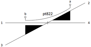
The functional model (alternative diagram) as used within an interlocking is shown below.
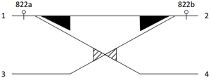
The model results in the combinations according to the table
| from track
|
to track
|
switch positions
|
| 1
|
2
|
822a-left / 822b-right
|
| 1
|
4
|
822a-right (822b-right)
|
| 3
|
2
|
822b-left (822a-left)
|
Considering the XML data of the double slip switch in chapter 1.1.1.2just the necessary changes are highlighted here. It starts with the <netRelations> as the single slip switch has only three possible paths to navigate. Subsequently the relation nr_a03a04 has to be revised, as it is not navigable in this example.
<netRelation id="nr_a03a04" navigability="None" positionOnA="1" positionOnB="0">
        <name name="rel324-822-333" language="en"/>
        <elementA ref="ne_a03" />
        <elementB ref="ne_a04" />
</netRelation>
The <switchIS> element in infrastructure is revised by the removal of the second turning branch and the switch type.
<switchIS id="scrx01" type="singleSwitchCrossing">
        <name name="pt822" language="en"/>
        <straightBranch netRelationRef="nr_a01a04" />
        <straightBranch netRelationRef="nr_a03a02" />
        <turningBranch netRelationRef="nr_a01a02" />
</switchIS>
For an interlocking the single slip switch is a special case of the double slip switch because the model of two single switches require a position restriction. As visible from the combination table the situation of a-side in right position and the b-side in left position shall never occur. If the turning branch is on the other side of the single slip switch the condition has to be inverted.
<switchesIL>
<!--pt822a is the point machine physically on the right hand side but virtually left sided-->
        <switchIL maxThrowTime="PT10S" id="mov_02" numberOfFrogSwitchActuators="0" numberOfBladeSwitchActuators="1" >
                <designator register="_SimpleRegister" entry="pt822a"/>
                <refersTo ref="scrx01" />
                <hasTvdSection ref="tvd_01" />
                <relatedMovableElement ref="mov_03" />
                <branchLeft ref="trk03" />
                <branchRight ref="trk01" />
                <hasPositionRestriction restrictedPosition="right">
                        <relatedSwitchInPosition id="res822a" inPosition="right">
                                <refersToSwitch ref="mov_03" />
                        </relatedSwitchInPosition>
                </hasPositionRestriction>
        </switchIL>
<!--pt822b is the point machine physically on the left hand side but virtually right sided-->
        <switchIL maxThrowTime="PT10S" id="mov_03" numberOfFrogSwitchActuators="0" numberOfBladeSwitchActuators="1" >
                <designator register="_SimpleRegister" entry="pt822b"/>
                <refersTo ref="scrx01" />
                <hasTvdSection ref="tvd_01" />
                <relatedMovableElement ref="mov_02" />
                <branchLeft ref="trk02" />
                <branchRight ref="trk04" />
                <hasPositionRestriction restrictedPosition="left">
                        <relatedSwitchInPosition id="res822b" inPosition="left">
                                <refersToSwitch ref="mov_02" />
                        </relatedSwitchInPosition>
                </hasPositionRestriction>
        </switchIL>
</switchesIL>
Coupled Switches
Coupled switches are mainly configured at crossovers between parallel tracks. They are always operated at once. Thus both of them are synchronised in branching or straight position. The interlocking just need to know the relation itself. The synchronised combination of both switch positions can be derived from the topology.
In the example of coupled switches the relation between both switches is marked by using the element <relatedMovableElement>. In addition it shall be ensured that any other attributes of these switches are not contradictionary, e.g. @returnsToPreferredPosition.
<switchIL returnsToPreferredPosition="true" id="pt_swi02" isKeyLocked="false" maxThrowTime="PT10S" typicalThrowTime="PT6S" preferredPosition="left">
        <designator register="_SimpleRegister" entry="69W03"/>
        <refersTo ref="swi02" />
        <relatedMovableElement ref="pt_swi03" />
        <branchLeft ref="trc04" />
        <branchRight ref="trc07" />
</switchIL>
<switchIL returnsToPreferredPosition="true" id="pt_swi03" isKeyLocked="false" maxThrowTime="PT10S" typicalThrowTime="PT6S" preferredPosition="left">
        <designator register="_SimpleRegister" entry="69W04"/>
        <refersTo ref="swi03" />
        <relatedMovableElement ref="pt_swi02" />
        <branchLeft ref="trc06" />
        <branchRight ref="trc07" />
</switchIL>
Dependency with Derailer
Some operators might configure a dependency between a derailer and the switch leading towards the derailer. The normal sequence will be that the derailer has to be switched to passable position before the related switch can be switched in the position towards the derailer. After use the switch has to be switched first into the protecting position before the derailer can be switched into the derailing position. This shall reduce the risk of unintended derailing during shunting movements.
The example shows the relation between switch swi03 and derailer der01 by using the element <relatedMovableElement>.
<switchesIL>
        <switchIL returnsToPreferredPosition="true" id="pt_swi03" isKeyLocked="false" maxThrowTime="PT10S" typicalThrowTime="PT6S" preferredPosition="left">
                <designator register="_SimpleRegister" entry="69W04"/>
                <refersTo ref="swi03" />
                <relatedMovableElement ref="dr_der01" />
                <branchLeft ref="trc06" />
                <branchRight ref="trc07" />
                <hasPositionRestriction restrictedPosition="left">
                        <relatedDerailerInPosition inPosition="passablePosition">
                                <refersToDerailer ref="dr_der01" />
                        </relatedDerailerInPosition>
                </hasPositionRestriction>
        </switchIL>
</switchesIL>
<derailersIL>
        <derailerIL returnsToPreferredPosition="true" id="dr_der01" isKeyLocked="false" maxThrowTime="PT10S" typicalThrowTime="PT6S" preferredPosition="derailingPosition">
                <designator register="_SimpleRegister" entry="69GS04"/>
                <refersTo ref="der01"/>
                <relatedMovableElement ref="pt_swi03" />
                <hasPositionRestriction restrictedPosition="derailingPosition">
                        <relatedSwitchInPosition inPosition="right">
                                <refersToSwitch ref="pt_swi03" />
                        </relatedSwitchInPosition>
                </hasPositionRestriction>
        </derailerIL>
</derailersIL>
Additional Information
Notes
Open Issues
- ↑ Dependent on the language variant there are several terms in use: point, turnout, switch. railML will use the term „switch“.


