|
|
| Line 10: |
Line 10: |
| {{importComment}} | | {{importComment}} |
| =={{examples}}== | | =={{examples}}== |
| | | ===Generic I/O-Interface=== |
| An interlocking can have several interfaces of different type with field elements and neighbouring interlockings. If the connecting components are from the same supplier, their interfaces to the interlocking do not need to be defined in a special way. Third party components usually have interfaces with rather individual features. Thus it needs to be defined which information is exchanged and in which way to allow a clear description of the interface. The information may be transferred by particular telegrams, bit masks and/or relays. Independent of the physical implementation it ends up with a list of commands/messages send in either direction as well as the related initial status assumed on start-up. | | An interlocking can have several interfaces of different type with field elements and neighbouring interlockings. If the connecting components are from the same supplier, their interfaces to the interlocking do not need to be defined in a special way. Third party components usually have interfaces with rather individual features. Thus it needs to be defined which information is exchanged and in which way to allow a clear description of the interface. The information may be transferred by particular telegrams, bit masks and/or relays. Independent of the physical implementation it ends up with a list of commands/messages send in either direction as well as the related initial status assumed on start-up. |
|
| |
|
| Line 27: |
Line 27: |
| **{{@|comString}} – The states of the single commands are represented within one bitmask string. Their order is related to the {{@|bitNr}} defined in the command description. The allowed values within the string are {{enum|0}} for inactive command, {{enum|1}} for active command and {{enum|x}} for command does not matter. | | **{{@|comString}} – The states of the single commands are represented within one bitmask string. Their order is related to the {{@|bitNr}} defined in the command description. The allowed values within the string are {{enum|0}} for inactive command, {{enum|1}} for active command and {{enum|x}} for command does not matter. |
| **{{@|messString}} – This is the representation of the single messages status. The use is the same as for the {{@|comString}}. | | **{{@|messString}} – This is the representation of the single messages status. The use is the same as for the {{@|comString}}. |
| | === Sample Interface for NOR Level Crossing === |
| | A level crossing is a typical field element with a special interface to the interlocking. Here is the example of a particular level crossing type as used in Norway. The first picture show the signal flow in an overview. |
| | |
| | [[File:Interface1.png]] |
| | |
| | The signal flow is amended by the detailed list of inputs and outputs whereas input is seen as command to the level crossing side. This is because the interface lists are typically provided by the supplier of the level crossing. |
| | |
| | |
| | {| style="border-spacing:0;width:16.249cm;" |
| | |- style="background-color:#dfdfdf;border:0.5pt solid #000000;padding-top:0cm;padding-bottom:0cm;padding-left:0.199cm;padding-right:0.191cm;" |
| | !| Input |
| | !| Function |
| | !| Normal state |
| | !| Name (Command) |
| | |- |
| | | style="border:0.5pt solid #000000;padding-top:0cm;padding-bottom:0cm;padding-left:0.199cm;padding-right:0.191cm;" | I 14 |
| | | style="border:0.5pt solid #000000;padding-top:0cm;padding-bottom:0cm;padding-left:0.199cm;padding-right:0.191cm;" | Remote deactivation, ch.1 |
| | | style="border:0.5pt solid #000000;padding-top:0cm;padding-bottom:0cm;padding-left:0.199cm;padding-right:0.191cm;" | NOT active, open circuit |
| | | style="border:0.5pt solid #000000;padding-top:0cm;padding-bottom:0cm;padding-left:0.199cm;padding-right:0.191cm;" | Deactivate 1 (C1) |
| | |- |
| | | style="border:0.5pt solid #000000;padding-top:0cm;padding-bottom:0cm;padding-left:0.199cm;padding-right:0.191cm;" | I 15 |
| | | style="border:0.5pt solid #000000;padding-top:0cm;padding-bottom:0cm;padding-left:0.199cm;padding-right:0.191cm;" | Remote deactivation, ch.2 |
| | | style="border:0.5pt solid #000000;padding-top:0cm;padding-bottom:0cm;padding-left:0.199cm;padding-right:0.191cm;" | NOT active, open circuit |
| | | style="border:0.5pt solid #000000;padding-top:0cm;padding-bottom:0cm;padding-left:0.199cm;padding-right:0.191cm;" | Deactivate 2 (C1 / C2 ) |
| | |- |
| | | style="border:0.5pt solid #000000;padding-top:0cm;padding-bottom:0cm;padding-left:0.199cm;padding-right:0.191cm;" | I 16 |
| | | style="border:0.5pt solid #000000;padding-top:0cm;padding-bottom:0cm;padding-left:0.199cm;padding-right:0.191cm;" | Activation, both directions |
| | | style="border:0.5pt solid #000000;padding-top:0cm;padding-bottom:0cm;padding-left:0.199cm;padding-right:0.191cm;" | NOT active, closed circuit |
| | | style="border:0.5pt solid #000000;padding-top:0cm;padding-bottom:0cm;padding-left:0.199cm;padding-right:0.191cm;" | Activate (C3) |
| | |- |
| | | style="border:0.5pt solid #000000;padding-top:0cm;padding-bottom:0cm;padding-left:0.199cm;padding-right:0.191cm;" | I 19 |
| | | style="border:0.5pt solid #000000;padding-top:0cm;padding-bottom:0cm;padding-left:0.199cm;padding-right:0.191cm;" | Activation direction A |
| | | style="border:0.5pt solid #000000;padding-top:0cm;padding-bottom:0cm;padding-left:0.199cm;padding-right:0.191cm;" | NOT active, closed circuit |
| | | style="border:0.5pt solid #000000;padding-top:0cm;padding-bottom:0cm;padding-left:0.199cm;padding-right:0.191cm;" | Enable A (C4) |
| | |- |
| | | style="border:0.5pt solid #000000;padding-top:0cm;padding-bottom:0cm;padding-left:0.199cm;padding-right:0.191cm;" | I 20 |
| | | style="border:0.5pt solid #000000;padding-top:0cm;padding-bottom:0cm;padding-left:0.199cm;padding-right:0.191cm;" | Activation direction B |
| | | style="border:0.5pt solid #000000;padding-top:0cm;padding-bottom:0cm;padding-left:0.199cm;padding-right:0.191cm;" | NOT active, closed circuit |
| | | style="border:0.5pt solid #000000;padding-top:0cm;padding-bottom:0cm;padding-left:0.199cm;padding-right:0.191cm;" | Enable B (C5) |
| | |- |
| | |} |
| | |
| | |
| | |
| | {| style="border-spacing:0;width:16.249cm;" |
| | |- style="background-color:#dfdfdf;border:0.5pt solid #000000;padding-top:0cm;padding-bottom:0cm;padding-left:0.199cm;padding-right:0.191cm;" |
| | !| Output |
| | !| Function |
| | !| Normal state |
| | !| Name (Message) |
| | |- |
| | | style="border:0.5pt solid #000000;padding-top:0cm;padding-bottom:0cm;padding-left:0.199cm;padding-right:0.191cm;" | O 05 (V) |
| | | style="border:0.5pt solid #000000;padding-top:0cm;padding-bottom:0cm;padding-left:0.199cm;padding-right:0.191cm;" | LC not activated, both directions |
| | | style="border:0.5pt solid #000000;padding-top:0cm;padding-bottom:0cm;padding-left:0.199cm;padding-right:0.191cm;" | active, closed circuit |
| | | style="border:0.5pt solid #000000;padding-top:0cm;padding-bottom:0cm;padding-left:0.199cm;padding-right:0.191cm;" | Opened (M1) |
| | |- |
| | | style="border:0.5pt solid #000000;padding-top:0cm;padding-bottom:0cm;padding-left:0.199cm;padding-right:0.191cm;" | O 06 (SR.W) |
| | | style="border:0.5pt solid #000000;padding-top:0cm;padding-bottom:0cm;padding-left:0.199cm;padding-right:0.191cm;" | Train signals cleared |
| | | style="border:0.5pt solid #000000;padding-top:0cm;padding-bottom:0cm;padding-left:0.199cm;padding-right:0.191cm;" | NOT active, open circuit |
| | | style="border:0.5pt solid #000000;padding-top:0cm;padding-bottom:0cm;padding-left:0.199cm;padding-right:0.191cm;" | Protected (M2) |
| | |- |
| | |} |
| | |
| | |
| | Finally the detailed list of inputs and outputs are transformed into the equivalent in railML as shown below. |
| | |
| | <syntaxhighlight lang=xml> |
| | <interface id="int01" invalidTolerationTime="PT0.5S" switchoverTolerationTime="PT0.8S"> |
| | <designator register="_SimpleRegister" entry="Level crossing Norge"/> |
| | <command bitNr="1" description="Remote deactivation, ch.1" id="I14" normalState="open"> |
| | <designator register="_SimpleRegister" entry="deactivate1"/> |
| | </command> |
| | <command bitNr="2" description="Remote deactivation, ch.2" id="I15" normalState="open"> |
| | <designator register="_SimpleRegister" entry="deactivate2"/> |
| | </command> |
| | <command bitNr="3" description="Activation, both directions" id="I16" normalState="closed"> |
| | <designator register="_SimpleRegister" entry="activate"/> |
| | </command> |
| | <command bitNr="4" description="Activation direction A" id="I19" normalState="closed"> |
| | <designator register="_SimpleRegister" entry="enableA"/> |
| | </command> |
| | <command bitNr="5" description="Activation direction B" id="I20" normalState="closed"> |
| | <designator register="_SimpleRegister" entry="enableB"/> |
| | </command> |
| | <message bitNr="1" description="LC not activated, both directions" id="O05" normalState="closed"> |
| | <designator register="_SimpleRegister" entry="Opened"/> |
| | </message> |
| | <message bitNr="2" description="Train signals cleared" id="O06" normalState="open"> |
| | <designator register="_SimpleRegister" entry="Protected"/> |
| | </message> |
| | <initStatus comString="00111" messString="10"/> |
| | </interface> |
| | </syntaxhighlight> |
|
| |
|
| =={{Additional Information}}== | | =={{Additional Information}}== |
| ==={{Notes}}=== | | ==={{Notes}}=== |
| ==={{Open issues}}=== | | ==={{Open issues}}=== |
Introduction
Documentation
Syntax
Autoexport from the XML-Schema for element IL:interface of railML ® version 3.2 |
| Documentation
|
Description of a physical interface with definition of the information to be exchanged in which direction.
|
| Subschema
|
interlocking
|
| Parents*
|
interfaces
|
| Children
|
assetName (0..*), belongsToOperationalPoint (0..1), command (0..*), designator (0..*), hasCommand (0..*), hasIndication (0..*), initStatus (0..1), message (0..*)
|
Attributes:
- invalidTolerationTime: The time period for which an invalid status of the received messages is tolerated. (optional;
xs:duration),
- switchoverTolerationTime: The time period for which the received messages are not considered stable due to switching process. (optional;
xs:duration),
- elementNumber: element number for internal referencing in the engineering data (optional;
xs:nonNegativeInteger),
- id: unique identifier (obligatory;
xs:string; patterns: (urn:uuid:)?[0-9a-fA-F]{8}-[0-9a-fA-F]{4}-[0-9a-fA-F]{4}-[0-9a-fA-F]{4}-[0-9a-fA-F]{12}|{[0-9a-fA-F]{8}-[0-9a-fA-F]{4}-[0-9a-fA-F]{4}-[0-9a-fA-F]{4}-[0-9a-fA-F]{12}}); compare: Dev:Identities
|
*Notice:
Elements may have different parent elements. As a consequence they may be used in different contexts.
Please, consider this as well as a user of this wiki as when developing this documentation further.
Aspects that are only relevant with respect to one of several parents should be explained exclusively in the documentation of the respective parent element.
|
Autoexport from the XML-Schema for element IL:interface of railML ® version 3.1 |
| Documentation
|
Description of a physical interface with definition of the information to be exchanged in which direction.
|
| Subschema
|
interlocking
|
| Parents*
|
interfaces
|
| Children
|
any (0..*), command (0..*), designator (0..1), initStatus (0..1), message (0..*)
|
Attributes:
- invalidTolerationTime: The time period for which an invalid status of the received messages is tolerated. (optional;
xs:duration),
- switchoverTolerationTime: The time period for which the received messages are not considered stable due to switching process. (optional;
xs:duration),
- id: unique identifier (optional;
xs:ID; patterns: (urn:uuid:)?[0-9a-fA-F]{8}-[0-9a-fA-F]{4}-[0-9a-fA-F]{4}-[0-9a-fA-F]{4}-[0-9a-fA-F]{12}|{[0-9a-fA-F]{8}-[0-9a-fA-F]{4}-[0-9a-fA-F]{4}-[0-9a-fA-F]{4}-[0-9a-fA-F]{12}}); compare: Dev:Identities
|
*Notice:
Elements may have different parent elements. As a consequence they may be used in different contexts.
Please, consider this as well as a user of this wiki as when developing this documentation further.
Aspects that are only relevant with respect to one of several parents should be explained exclusively in the documentation of the respective parent element.
|
Changes 3.1→3.2
The children have changed.
The attributes have been changed.
Semantics
Best Practice / Examples
Generic I/O-Interface
An interlocking can have several interfaces of different type with field elements and neighbouring interlockings. If the connecting components are from the same supplier, their interfaces to the interlocking do not need to be defined in a special way. Third party components usually have interfaces with rather individual features. Thus it needs to be defined which information is exchanged and in which way to allow a clear description of the interface. The information may be transferred by particular telegrams, bit masks and/or relays. Independent of the physical implementation it ends up with a list of commands/messages send in either direction as well as the related initial status assumed on start-up.
Per definition “commands” is named anything send from the interlocking to the connecting component via the interface, i.e. orders to the field. On the other side “messages” is named anything received at the interface for the interlocking, i.e. notifications from the field.
The interface is described by the following attributes and elements
- @invalidTolerationTime – This is the time an invalid status of commands or messages is tolerated before a failure action is performed.
- @switchoverTolerationTime – This is the time it will take for a command or message to switch over before a stable status is expected.
- <command> – This contains the description of a command send from the interlocking to the field element.
- @bitNr – This is the order number of the command in the list. In case of transmission as complete bitmask it defines the bit position in the byte.
- @description – This is just the description/meaning of the command send.
- @normalState – This gives the normal state of the command when not energised. The values are derived from relay contacts. Thus open means open contact, inactive command state or false depending on the particular technology. In contrast closed stands for a closed contact, an active command state or true.
- @pulseDuration – This is the time for the related command being in the reverse state if no permanent switchover is done.
- <message> – This contains the description of a message received by the interlocking from the field element. The attributes are the same as for a <command>.
- <initStatus> – This is the description of the interface status in command and message direction which is assumed in start-up cases, i.e. when both sides of the system are just powered up.
- @comString – The states of the single commands are represented within one bitmask string. Their order is related to the @bitNr defined in the command description. The allowed values within the string are 0 for inactive command, 1 for active command and x for command does not matter.
- @messString – This is the representation of the single messages status. The use is the same as for the @comString.
Sample Interface for NOR Level Crossing
A level crossing is a typical field element with a special interface to the interlocking. Here is the example of a particular level crossing type as used in Norway. The first picture show the signal flow in an overview.
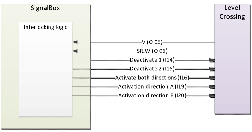
The signal flow is amended by the detailed list of inputs and outputs whereas input is seen as command to the level crossing side. This is because the interface lists are typically provided by the supplier of the level crossing.
| Input
|
Function
|
Normal state
|
Name (Command)
|
| I 14
|
Remote deactivation, ch.1
|
NOT active, open circuit
|
Deactivate 1 (C1)
|
| I 15
|
Remote deactivation, ch.2
|
NOT active, open circuit
|
Deactivate 2 (C1 / C2 )
|
| I 16
|
Activation, both directions
|
NOT active, closed circuit
|
Activate (C3)
|
| I 19
|
Activation direction A
|
NOT active, closed circuit
|
Enable A (C4)
|
| I 20
|
Activation direction B
|
NOT active, closed circuit
|
Enable B (C5)
|
| Output
|
Function
|
Normal state
|
Name (Message)
|
| O 05 (V)
|
LC not activated, both directions
|
active, closed circuit
|
Opened (M1)
|
| O 06 (SR.W)
|
Train signals cleared
|
NOT active, open circuit
|
Protected (M2)
|
Finally the detailed list of inputs and outputs are transformed into the equivalent in railML as shown below.
<interface id="int01" invalidTolerationTime="PT0.5S" switchoverTolerationTime="PT0.8S">
        <designator register="_SimpleRegister" entry="Level crossing Norge"/>
        <command bitNr="1" description="Remote deactivation, ch.1" id="I14" normalState="open">
                <designator register="_SimpleRegister" entry="deactivate1"/>
        </command>
        <command bitNr="2" description="Remote deactivation, ch.2" id="I15" normalState="open">
                <designator register="_SimpleRegister" entry="deactivate2"/>
        </command>
        <command bitNr="3" description="Activation, both directions" id="I16" normalState="closed">
                <designator register="_SimpleRegister" entry="activate"/>
        </command>
        <command bitNr="4" description="Activation direction A" id="I19" normalState="closed">
                <designator register="_SimpleRegister" entry="enableA"/>
        </command>
        <command bitNr="5" description="Activation direction B" id="I20" normalState="closed">
                <designator register="_SimpleRegister" entry="enableB"/>
        </command>
        <message bitNr="1" description="LC not activated, both directions" id="O05" normalState="closed">
                <designator register="_SimpleRegister" entry="Opened"/>
        </message>
        <message bitNr="2" description="Train signals cleared" id="O06" normalState="open">
                <designator register="_SimpleRegister" entry="Protected"/>
        </message>
        <initStatus comString="00111" messString="10"/>
</interface>
Additional Information
Notes
Open Issues
