UC:IL:InterlockingEngineering
| Interlocking module engineering data Subschema: Interlocking | ||||
| ||||
| For general information on use cases see UC:Use cases |
Use case / Anwendungsfall
Interlocking module engineering data ; Stellwerksprojektierung
Description / Beschreibung
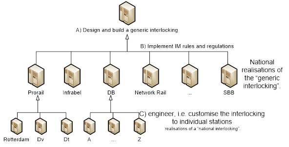
The process of creating an interlocking is three-tiered.
- The manufacturer designs an interlocking platform with an operating system and appropriate hardware to operate field elements such as points, signals, track sections, axle counters, etc.
- The manufacturer implements the Infrastructure Manager’s (IM) rules and regulations (german Betriebsordnung) in software. The behaviour of the interlocking is customised to meet the IM’s requirements. This stage is a one-off process per IM and includes functions particular to railway administrations such as overlap, signal aspects and flank protection. Once these national rules have been implemented in generic software, they remain fixed. The functional behaviour of an interlocking now reflects the IM’s rulebook for interlocking.
- Customise, i.e. engineer, the interlocking to match individual stations. The interlocking is custom-tailored to operate points, sections, signals and so on. This engineering process (Projektierung) of course depends on the layout of the individual station. Every interlocking is different.
Stage C, the engineering process, is extremely costly. The overwhelming majority of data are taken from (paper) plans. Data exchange between IM and supplier takes the shape of graphical plans, tables or plain language requirement documents. These plans often are a print-out from suppliers proprietary tools. The manual conversion of the data from paper into the supplier’s tool chain is likely to introduce errors that must be found and corrected by testing.
Automated exchange and conversion of railML data, rather than picking data from paper plans, into the suppliers tool chain will reduce cost. Better still, if the input data are known to be correct, validation costs will fall drastically. The latter should be the principal reason to adopt a common exchange format.
This use case concerns the exchange of engineering data for tailoring an interlocking to fit a station.
This use case focuses on "legacy" interlockings and signalling systems. The latter indicates that data can be used for the purpose of configuring ETCS systems. Note that the Eulynx project, with whom railML cooperates, defines data in terms of types and attributes mainly for the purpose of asset Management. These Eulynx-defined asset data are internal to the IM whereas railML focuses on data exchange. Infrastructure Managers keep planning data needed to build an interlocking that they wish to convey to suppliers of interlocking equipment in a standard format. Note that data are safety relevant and must respect the restrictions of signalling rules of the railways. To-build data flow from IM to suppliers. The latter enrich the data with specific design information that flows back to the Infrastructure Manager (as-built). To-build and as-built data will be in railML format.
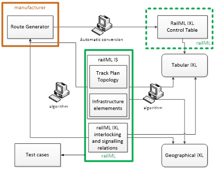
Above figure shows the position of railML in the data exchange process.
Data Flows and Interfaces / Datenflüsse und Schnittstellen
The railML IL scheme will hold data that manufacturers’ tools can easily extract.
Information Category:
- Topology (origin: railML IS schema or classic track plan)
- Track Elements (signals, points, sections…) (origin: railML IS schema or classic track plan)
- Interlocking relations (origin: railML IS schema or classic track plan or plain text requirements.)
- Control tables (origin: Track plan or spreadsheets)
- Signal aspect relations (origin: Classic signal plan)
- Signalled speeds (origin: Classic signal plan)
- Timers (e.g. for throwing points, revoking signals, etc) (origin: Railway regulations or other plain text requirements)
The focus should be on data reliability because IL and IS data will be used for producing SIL-4 interlocking.
Interference with other railML® schemas / Interferenz mit anderen railML®-Schemen
Main input for interlocking engineering are the track elements points, signals, sections. The interlocking needs to know the properties of these elements and their topology that the Infrastructure Schema describes. Therefore, the railML IL scheme will extensively refer to track elements that are defined in the IS scheme. The version of the IS scheme (3.0, 3.1, ...) will be less relevant.
The new IL schema will mainly model interlocking relations between infrastructure elements.
See also: Exchange of planning parameters for interlocking with suppliers
Characterizing Data / Charakterisierung der Daten
This section serves to specify the required data regarding certain aspects.
| Main items | Detailed description |
|---|---|
| Topology | Inclusion of use case "Schematic Track Plan" (SCTP) |
| Track | IS:Track
- relation to neighbours: IS:track (trackBegin, trackEnd) |
| TVD section | IL:TvdSection
- relation to track(s): indirect via position of delimiting elments |
| Switch/Derailer | IS:SwitchIS / IL:SwitchIL, IS:DerailerIS / IL:DerailerIL, IS:Crossing / IL:MovableCrossing
- relation to TVD section: @hasTvdSection |
| Key lock | IS:KeyLockIS / IL:KeyLockIL
- relation to the keylocked element: @takesControlOf |
| Signal | IS:SignalIS / IL:SignalIL
- basic functional type for main signals (entry/exit/junction/intermediate/ block): signalIL@function |
| Level crossing | IS:LevelCrossingIS / IL:LevelCrossingIL
- basic type definition (autonomous, half/one sided controlled, full controlled): IL:LevelCrossingIL @isLevelCrossingType |
| Interlocking interface | IL:SignalBox @controlsInterface
- interface location (in station, at station border, on open line): IL:controlsInterface @interfaceLocation |
| Local operation | IL:LocalOperationArea
- related elements limiting the area: IL:RestrictedArea @isLimitedBy |
| Route | IL:Route, IL:SignalPlan
- Route approach area: IL:Route @routeActivationSection |
| Power Supply | IL:PowerSupplyIL
- Number of points activated simultaneously per power supply: @numberOfSimultaneousSwitchingActuators |
| Element grouping | Grouping of elements for various operational purposes
- call-on |
How often do the data change (update)?
Depends on the frequency of resignalling, public works, corrections. Order of magnitude for a single station is 1/month – 1/decade. A typical modification is removal of a point. This suggests that the frequency of update is fairly low.
How big are the data fragments to be exchanged (complexity)?
The size of the data to be exchanged typically match the size of an interlocking area, i.e. a station. The size of the railML IL file grows linearly with the number of routes and exponentially with the number of network nodes.
Which views are represented by the data (focus)?
- Signalling
- Schematic view of topology (Indispensable for interlocking engineers used to graphic presentation of signaling plans)
Interlocking engineers need the schematic view of data, i.e. a graphical representation of IL data because they are used to signal plans and track plans. Therefore, the railML data must contain coordinates that allow plotting schematic views. Such views support validation. Signalling engineers will only accept railML if combined with easy-to-use graphical tools. These tools must show obvious advantages with respect to the conventional way of working with paper plans and spreadsheets.

